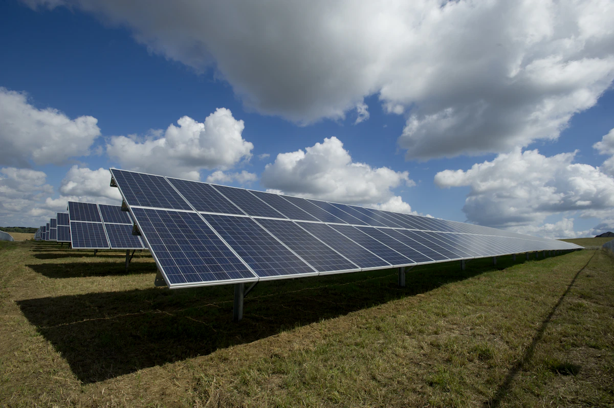
Solar PV
Twenty years of EPC and O&M — from premium villas to utility-scale desert plants under national utility frameworks.
A Global Energy Transition Group — Engineered to International Standards
Not predicted. Not promised. Built — panel by panel, well by well, molecule by molecule. We develop, finance, supply and construct the systems that will power the next century.
Why we exist
Every light in every home. Every hospital, every school, every idea that needed power to become real. Energy is not an industry. It is the quiet force behind every human life — and for the first time in history, we can make it clean, endless, and for everyone. That is the work of our lifetime. That is Smart Gulf Energy.
We don't power machines. We power life.Interlude — The Living Grid
Six divisions, one group
Twenty years of EPC and O&M — from premium villas to utility-scale desert plants under national utility frameworks.

Grid-scale BESS and hybrid plants, delivered EPC or EPC+F.
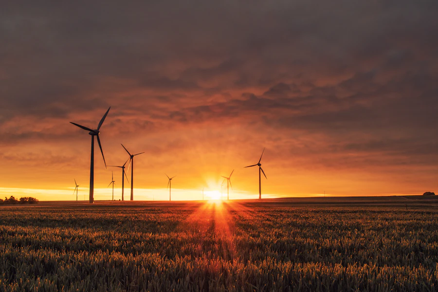
Electrolysis development where the world's cheapest solar lives.

CCUS backed by proprietary research and national cooperation.
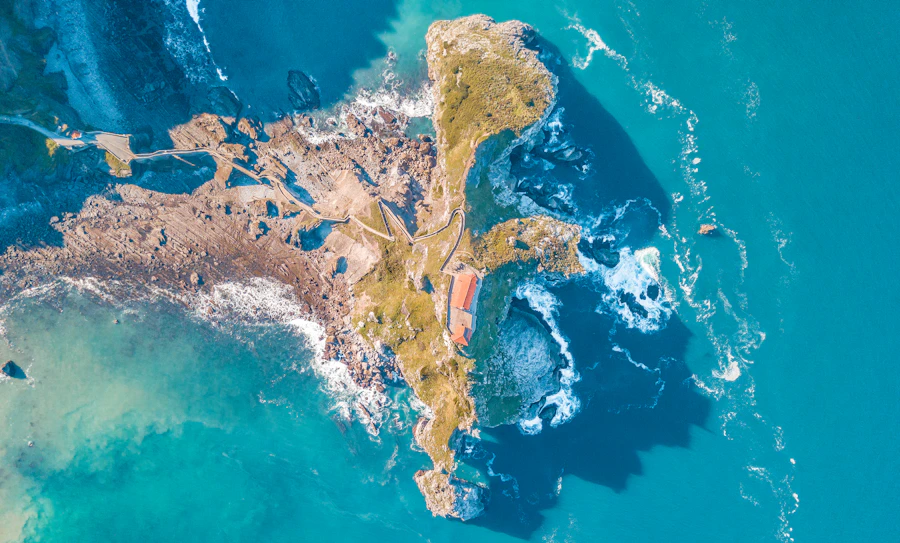
Around-the-clock clean heat and power, built on our drilling heritage.
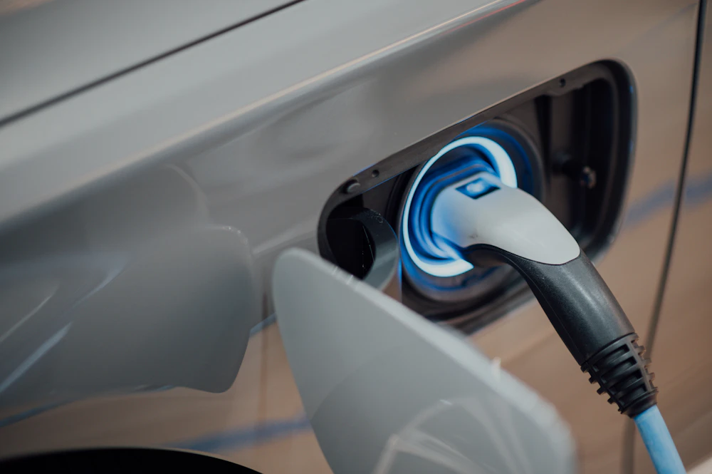
Charging networks powered by our own solar and storage — clean generation to clean mobility, closed loop.
Bankable feasibility, tender engineering and EPC+F structuring for governments, utilities, DFIs and investors.
How we work
Site origination, feasibility, permitting, PPAs and bankable tender packages. We create projects — not just bid on them.
EPC+F structures with international partners, DFIs and family offices — including Shariah-compliant options.
Direct procurement of modules, inverters, batteries, electrolysers and chargers from tier-one manufacturers.
Full EPC and long-term O&M — two decades of delivery behind every commissioning certificate.
Systems engineering
The full anatomy of each technology — how it works, the components it needs, and how we install it. Select a system.
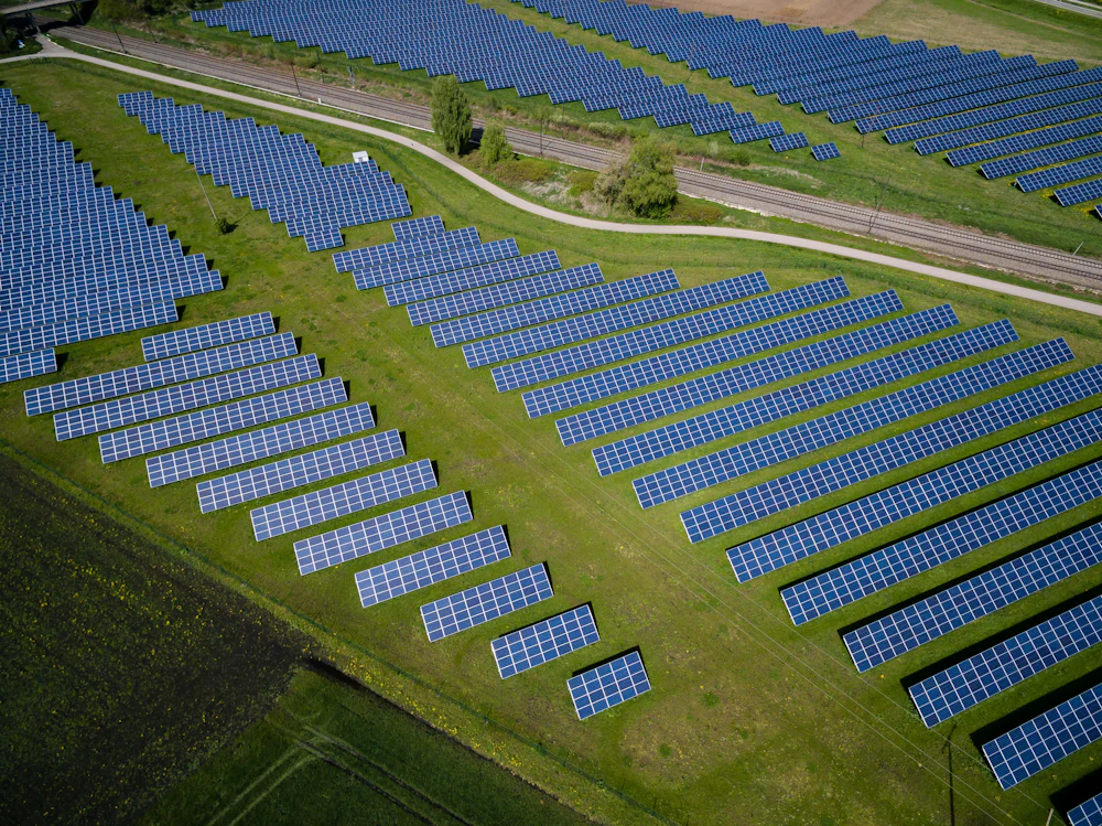
How it works: photons strike silicon cells and knock electrons loose — direct current. Strings of modules feed inverters that convert DC to grid-quality AC, a transformer steps up the voltage, and the meter counts every kilowatt-hour you sell.
Fig. 01 — Solar PV single line: sun to grid
Mono PERC / TOPCon panels, 550–700 Wp each — the generators.
Aluminium rails and clamps (rooftop) or galvanised steel piles and trackers (ground mount).
Convert DC to AC with MPPT tracking; 1 per 100–350 kWp block typically.
Solar DC cable, connectors, combiner boxes with fuses and surge protection.
Breakers, isolators, SPDs, lightning protection and grounding grid.
Bidirectional utility meter plus cloud monitoring for every string.
Site assessment, shading analysis, structural checks, and utility application.
Week 1Anchoring or piling, rails levelled and torqued to specification.
Week 2Panels mounted, clamped and string-wired per the electrical design.
Week 2–3Inverters, combiner boxes, AC distribution and earthing completed.
Week 3–4Insulation, polarity and IV-curve tests; utility inspection and meter installation.
Week 4–5Grid connection approved, monitoring live, O&M plan handed to the client.
Week 5–6How it works: lithium-iron-phosphate cells store energy chemically. A battery management system guards every cell; the power conversion system charges and discharges in milliseconds on command from the energy management system — shifting cheap midday solar into the evening peak.
Fig. 02 — Grid-scale BESS architecture
LiFePO4 cells assembled into modules and racks — the energy store itself.
Monitors voltage, current and temperature of every cell; isolates faults instantly.
Bidirectional inverter charging and discharging the DC battery to the AC grid.
Liquid cooling or HVAC keeping cells in their safe temperature window.
Gas detection, aerosol or clean-agent suppression, deflagration venting.
Dispatch intelligence, utility communications, and MV step-up connection.
Interconnection study, dispatch use-case design, layout and safety engineering.
Month 1–2Foundations, cable trenches, firewalls and access roads.
Month 2–4Battery and PCS containers craned onto foundations, aligned and anchored.
Month 4–6DC bus, AC collection, transformer and protection systems connected.
Month 6–8Cell balancing, capacity tests, grid-code compliance and dispatch trials.
Month 8–12How it works: renewable electricity splits purified water into hydrogen and oxygen inside an electrolyser — 2H2O → 2H2 + O2. The hydrogen is compressed and stored, then shipped as ammonia, piped to industry, or dispensed to fuel-cell fleets. Roughly 50–55 kWh and nine litres of water per kilogram.
Fig. 03 — Green hydrogen: power and water to three offtakes
PEM or alkaline units — the heart of the plant where water splits.
Convert AC renewable power to the high-current DC the stacks need.
Desalination and ultra-pure polishing — nine litres per kilogram of H2.
Multi-stage compressors raising H2 to 350–700 bar for storage.
Pressure vessels or caverns, gas purification, cooling and piping.
H2 leak detection, ATEX-rated equipment, venting and flame arrestors.
Power source, water source, offtake contracts and front-end engineering.
Month 1–6Safety approvals, land, and long-lead orders for stacks and compressors.
Month 6–12Foundations, water intake, electrical substation and pipe racks.
Month 12–18Stacks, compressors, storage and balance of plant erected and piped.
Month 18–28Leak testing, purging, stack conditioning and first hydrogen.
Month 28–36How it works: flue gas passes through an amine solvent that absorbs over 90% of its CO2. Heat releases the pure CO2 from the solvent, compression makes it supercritical above 74 bar, and pipelines carry it to deep geological storage — below 800 metres, monitored for permanence.
Fig. 04 — CCUS chain: capture, compress, transport, store, verify
Tall packed tower where amine solvent scrubs CO2 from flue gas.
Heated column releasing pure CO2 and recycling the solvent.
Amine inventory, heat exchangers, reboiler and reclaimer.
Multi-stage compressors and dehydration to pipeline specification.
CO2-rated pipeline, wellheads and injection tubing to the reservoir.
Seismic, pressure and geochemical monitoring proving permanence — the basis of carbon credits.
Characterise the emitter's flue gas and qualify the geological storage site.
Month 1–8Front-end design, storage licence, environmental and safety approvals.
Month 8–18Columns, solvent systems and compression erected at the host facility.
Month 18–36Injection wells drilled and completed; transport pipeline laid and tested.
Month 24–44First injection, baseline monitoring and verification reporting begin.
Month 44–60How it works: production wells bring hot brine — 120 to 200°C — up from the reservoir. A heat exchanger transfers that heat to an organic working fluid that spins an ORC turbine, and the cooled brine returns underground through injection wells. A closed loop that never stops: 90%+ capacity factor, day and night.
Fig. 05 — Binary geothermal: heat from below, power above
Rig, casing, cementing and wellheads — the same craft as oil and gas drilling, our group's home ground.
Line-shaft or electric submersible pumps lifting brine to surface.
Transfer brine heat to the organic working fluid without mixing.
Organic Rankine Cycle turbine generating from low-temperature heat.
Air-cooled condensers returning the working fluid to liquid.
Pumps and injection wells closing the loop and sustaining the reservoir.
Geological surveys, gradient wells and reservoir modelling.
Month 1–8First wells confirm temperature and flow; the make-or-break phase.
Month 8–18Full production and injection well field completed.
Month 18–30ORC units, heat exchangers, cooling and substation built.
Month 30–42Well testing, plant tuning and continuous baseload generation.
Month 42–48How it works: grid power — supplemented by canopy solar and a buffer battery — feeds DC fast chargers that talk directly to the vehicle's battery. The battery buffer means a modest grid connection can still deliver ultra-fast charging, and the OCPP backend handles payment, load balancing and uptime.
Fig. 06 — Solar-buffered DC fast-charging hub
150–350 kW units with CCS2 / GB-T connectors and dynamic power sharing.
MV connection, LV distribution and protection for the full hub load.
Steel canopy shading vehicles while generating on-site solar power.
BESS that peak-shaves, letting a small grid connection deliver big charging power.
Charge-point management: payment, roaming, remote diagnostics, load balancing.
Foundations, bollards, cable trenches, lighting, CCTV and signage.
Traffic analysis, available grid capacity, and utility application.
Week 1–4Layout, electrical design, authority permits and operator agreements.
Week 4–8Foundations, trenching, ducting and canopy erection.
Week 8–14Transformer, switchgear, chargers, PV and battery connected.
Week 14–18Charger certification, backend integration, test charges and public opening.
Week 18–20How it works: wind pushes aerodynamic blades, spinning a rotor at 10–20 rpm. A gearbox (or direct drive) raises that to generator speed, a converter cleans the power to grid frequency, and a transformer in the tower base steps it up. Pitch and yaw systems constantly turn the blades and nacelle to harvest the most wind — and protect the machine in storms.
Fig. 07 — Wind turbine drivetrain: blades to grid
Composite blades up to 80m+ each — the collectors of the wind's energy.
The machine house converting slow rotation into electrical power.
Conditions variable output to exact grid frequency and voltage.
Steel tower sections on a massive reinforced concrete foundation.
Motors angling blades and turning the nacelle into the wind.
Inter-turbine MV cabling, substation and remote monitoring.
Met masts or lidar measure the wind for 12+ months.
Month 1–12Turbine layout, environmental studies and grid agreement.
Month 8–16Roads, crane pads and concrete foundations poured and cured.
Month 16–22Tower, nacelle and blades lifted by main crane — one turbine in days.
Month 22–28Electrical tests, grid-code compliance and performance verification.
Month 28–32How it works: thousands of mirrors — heliostats — track the sun and focus its light onto a receiver at the top of a tower, heating molten salt to over 560°C. The hot salt is stored in insulated tanks, so steam can be raised and the turbine can run long after sunset. This is solar power that works at midnight.
Fig. 08 — CSP power tower with molten salt storage
Thousands of dual-axis tracking mirrors focused on one point.
Central tower with the solar receiver absorbing concentrated light.
Nitrate salt inventory, hot and cold storage tanks, pumps and trace heating.
Salt-to-steam heat exchangers feeding the power block.
Conventional Rankine power block — proven utility hardware.
Air-cooled condensers suited to desert sites with scarce water.
DNI measurement, field optimisation and storage sizing.
Month 1–8Field grading, foundations and receiver tower construction.
Month 8–20Serial assembly and calibration of thousands of mirrors.
Month 14–30Tanks, steam generators and turbine installed; salt melted and charged.
Month 24–36Receiver tuning, storage cycling and first night-time generation.
Month 36–42How it works: municipal waste is combusted at over 850°C in a controlled furnace, raising steam that drives a turbine. Advanced flue-gas treatment scrubs the exhaust to strict emission limits, metals are recovered from the ash for recycling — and a city's waste problem becomes a city's power plant.
Fig. 09 — Waste-to-energy: from bunker to clean stack
Enclosed tipping hall with negative pressure and waste crane.
Combusts unsorted municipal waste above 850°C.
Raises superheated steam from the furnace's heat.
Converts steam to electricity — plus district heat or cooling.
Scrubbers, activated carbon and bag filters to strict EU-level limits.
Bottom-ash processing recovering steel and aluminium for recycling.
Waste composition analysis, environmental permits and offtake agreements.
Month 1–12Bunker excavation, main building and stack foundations.
Month 12–24Grate, boiler, turbine and flue-gas systems installed.
Month 24–38Substation, plant control system and emissions monitoring.
Month 34–42First fire, emissions verification and continuous operation trials.
Month 42–48How it works: a well is a precision-engineered steel and cement structure descending kilometres into the earth. Each casing string is cemented in place before drilling deeper — telescoping down from the wide conductor to the production casing. Inside runs the production tubing; a packer seals the annulus, a downhole pump lifts the fluid, and perforations connect the wellbore to the reservoir. This is our group's home craft — the same engineering that now unlocks geothermal, lithium brine and CO2 storage.
Fig. 10 — Downhole schematic: telescoping casing design, tubing, packer, pump and perforations
The rig turns the bit; the blowout preventer is the safety valve on top of the well.
Telescoping steel pipe — conductor, surface, intermediate, production — each cemented before drilling deeper.
Pumped down and up the annulus, bonding casing to rock and isolating every zone.
The replaceable flow path, sealed to the casing by the packer.
Electric submersible or line-shaft pump lifting brine or fluids to surface.
Surface valves controlling pressure and flow for the life of the well.
Casing programme, mud plan and trajectory engineered from geology.
Month 1–3Conductor and surface casing set and cemented — aquifers protected.
Month 3–4Section by section: drill, run casing, cement, pressure test, repeat.
Month 4–7Perforate the target zone, run tubing, set the packer, install the pump.
Month 7–8Flow testing confirms deliverability; the well begins its working life.
Month 8–9Describe your project and our Smart Quote Engine sizes the system, calculates ROI to international methodologies, and emails you a full preliminary quotation instantly — day or night. A specialist only steps in when you are ready to proceed.
Prices are all-in — including taxes, carbon and grid charges.
Our AI recommends the right system size — no numbers needed.
Preliminary estimate calculated to international methodologies (IEC 61724 performance ratio, IRENA cost benchmarks) using regional pricing with all-in tariffs (energy + taxes + carbon + grid charges). Final quotation follows a site survey and grid assessment. Deposit and payment details are shared personally by our commercial director after verification — never by automated email.
| Item | Component | Quantity |
|---|
This preliminary single line design follows IEC 60617 symbology. Final electrical drawings are certified by licensed engineers and approved by the relevant authority during permitting. Included in your emailed quotation.
The Smart Quote Engine sizes the system, prices it, and emails the client a welcome message with their full quotation, design and BOQ. You do nothing.
Every auto-quoted lead lands in your inbox marked "no action needed." The client explores, compares, returns — the site keeps selling.
When a client clicks "Proceed to Deposit," you receive a priority email marked ACTION REQUIRED — verify them personally and share payment instructions directly. Bank details are never automated.
The full spectrum
The complete atlas of energy production technology. Highlighted items are active Smart Gulf Energy divisions or development focus areas.
Highlighted — Smart Gulf Energy active division or development focus. We track the whole map so our clients build with what wins next, not what won last decade.
Delivery timelines
Typical durations from contract signature to commissioning, permits and grid approval included.
Certifications & approvals
Our quality, environmental and safety management systems — certified, audited, and continuously improved.
Certified quality management across engineering, procurement and construction operations.
CertifiedApproved solar contractor under the national utility's distributed solar programme.
ApprovedEnvironmental management system certification for sustainable project delivery.
Certification TrackOccupational health and safety management for every site, every crew, every day.
Certification TrackCommitting to the Compact's ten principles on human rights, labour, environment and anti-corruption.
Participation TrackProjects structured and reported against the UN Sustainable Development Goals framework.
ActiveEngineered to international standards
Our engineering, drawings and performance calculations follow these international standards. Final designs are certified by licensed engineers and approved by the relevant national authority during permitting.
What we plant in wire and silicon, our children harvest in light.Interlude — For the Next Generation
Global impact
A child studying after dark. A clinic that never loses its vaccines. A factory that hires a town. This is what a megawatt really means — and it is why we build alongside governments, development institutions and NGOs, from the Gulf to Africa and beyond.
Solar, storage and geothermal expanding access at falling cost.
Local jobs, skills and supply chains with every project.
Grids, storage and charging built as national assets.
Rooftop solar, EV charging and clean district energy.
CCUS and clean generation cutting CO2 at industrial scale.
Governments, DFIs, NGOs and private capital, together.
Who we work with
Newsroom
Announcements from the group, and our leadership's published writing across regional and international media.
Building on two decades of solar EPC delivery, the group unites six divisions — Solar, Battery Storage, Green Hydrogen, Carbon Capture, Geothermal and EV Infrastructure — under a single develop-finance-supply-build platform serving markets worldwide.
CorporateA comprehensive 128-page white paper on carbon capture, utilisation and storage anchors the group's research-led CCUS division, with peer-review-track journal manuscripts and cooperation with national energy entities underway.
ResearchThe group extends its delivery model into African markets, led by a 20 MW solar with 150 MWh battery storage tender submission structured as a full EPC-plus-financing package with international partners.
ProjectsFollow us in the press
Logos, executive bios, project imagery and interview requests — we respond within one business day.
In the field
Project inquiry
Share the essentials and the right division responds with a preliminary assessment within two business days.
Client portal
After your deposit is received, our commercial director emails you a personal Project ID and Access Key. Log in any time to see exactly where your project stands.
Demo access — Project ID: SGE-DEMO-001 · Key: DEMO-2026
—
sales@smartgulfsolar.com
info@smartgulfenergy.com
Within one business day, seven days a week
Contracts, drawings and certificates are shared securely by your project engineer at each stage.
Contact us
Partnerships, media, careers and general questions. For project quotations, use the inquiry form above.